Expert contributors for this post
Dr. Abhishek Deshmukh
Application Engineering Team Lead
Introduction
Grounded coplanar waveguides (GCPWs) are a type of planar transmission line widely used in high-frequency applications, including 5G and beyond wireless communication networks, automotive radar systems, and high-speed digital circuits. They offer a distinct advantage over other transmission line structures, such as microstrips, particularly at higher frequencies, due to their superior signal integrity and reduced dispersion.

Fig. 1
GCPWs consist of a central signal conductor separated from two grounded planes on the same substrate. This coplanar arrangement of the signal conductor and ground planes creates a strong confinement of the electromagnetic field, minimizing radiation losses and crosstalk. This field confinement is the key to GCPWs' excellent high-frequency performance, ensuring efficient signal transmission with minimal distortion.
Design challenges of GCPWs
Despite their advantages, designing GCPWs presents several challenges.
- Impedance matching: For optimal power transfer and to minimize signal reflections, the characteristic impedance of the GCPW must be carefully matched to the impedance of the source and load. Achieving this match often requires precise control over the GCPW's geometry.
- Parastic effects: GCPWs can be susceptible to parasitic effects, such as unwanted coupling to nearby components or external electromagnetic interference. These parasitic effects can degrade signal quality and must be carefully considered during the design process.
- Radiation and dielectric losses: Like all transmission lines, GCPWs experience some signal attenuation due to radiation losses and dielectric losses within the substrate material. Minimizing these losses is crucial for efficient signal transmission.
Impact of Quanscient Allsolve on design and optimization of GCPWs
We investigate the electromagnetic behavior of GCPWs using Maxwell's equations, solved with the finite element method (FEM).
The simulation setup includes detailed 3D geometric models incorporating signal conductors, ground planes, and FR4 dielectric substrates, with parameterized dimensions to facilitate design exploration.
Eigenmode and lumped ports are employed to model connections to external circuitry.
The accuracy of the simulations is validated by comparison with analytical calculations. A detailed analysis of the impact of different mesh types on simulation accuracy is presented. Comprehensive parametric sweeps explore the influence of key design parameters, including relative permittivity, frequency, track width, and dielectric thickness, on GCPW performance.
Furthermore, a design exploration study reveals the complex relationship between geometric parameters and characteristic impedance.
This highlights the exceptional performance of Quanscient Allsolve, enabling the efficient completion of a large-scale design exploration study (approximately 12,000 simulations) in a fraction of the time required by traditional desktop-based computing.
This demonstrates the power of cloud-based high-performance computing for accelerating the design and optimization of GCPWs and other complex high-frequency components.
Quanscient Allsolve
Scalable multiphysics simulations for MEMS design
See how Quanscient Allsolve expands MEMS design possibilities →
Case example
Simulation objective
Simulating GCPWs is essential for addressing these design challenges and optimizing their performance. Simulations provide valuable insights into the electromagnetic behavior of GCPWs, allowing engineers to:
- Understand properties: Gain a deeper understanding of the relationship between GCPW geometry and its electrical characteristics, such as impedance, effective permittivity, and losses.
- Optimize geometric design: Explore different geometric parameters to achieve desired performance targets, such as impedance matching and minimization of losses.
- Address miniaturization and packaging: Design compact GCPW structures for integration into increasingly smaller and more complex electronic devices. Simulations help to ensure performance is maintained even with size constraints.
- Explore innovative designs: Investigate new GCPW configurations and materials to further enhance performance and meet the demands of emerging high-frequency applications. Simulation allows for rapid prototyping and testing of these innovations.
The model
FEM was used to simulate how 3D GCPWs behave electromagnetically. FEM is a powerful numerical technique for solving partial differential equations, in this case, Maxwell's equations, which govern the behavior of electromagnetic fields. By discretizing the computational domain into a finite number of elements, FEM allows us to approximate the solution to Maxwell's equations and obtain detailed information about the electric and magnetic fields within and around the GCPW.
Allsolve's high-performance computing capabilities enable efficient solution of large-scale FEM problems, making it well-suited for the complex simulations and parametric studies presented in this work.
For these simulations, we assume that the material properties of the GCPW, such as the permittivity of the dielectric substrate, change slowly with respect to time. This assumption allows us to simplify Maxwell's equations by neglecting the time derivative of the material properties. This simplification is valid for the frequency range considered in this study.
To model the interaction of the GCPW with external circuitry, we utilize both eigenmode and lumped ports. Eigenmode ports are applied at one end of the GCPW to excite the fundamental propagating mode within the waveguide. Lumped ports are used at the other end to connect an external RLC circuit in series with the GCPW. This approach allows us to simulate the impact of the external circuit on the GCPW's performance.
Simulation setup
The simulation setup includes a detailed 3D geometric model of the GCPW, including the signal conductor, ground planes, and the FR4 dielectric substrate. The dimensions of the GCPW, such as the track width (w), gap between the signal and ground planes (s), and dielectric thickness (h), are parameterized to enable systematic design exploration.
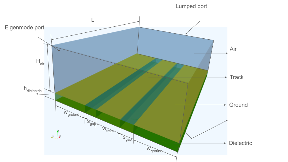
Fig. 2 GCPW geometry
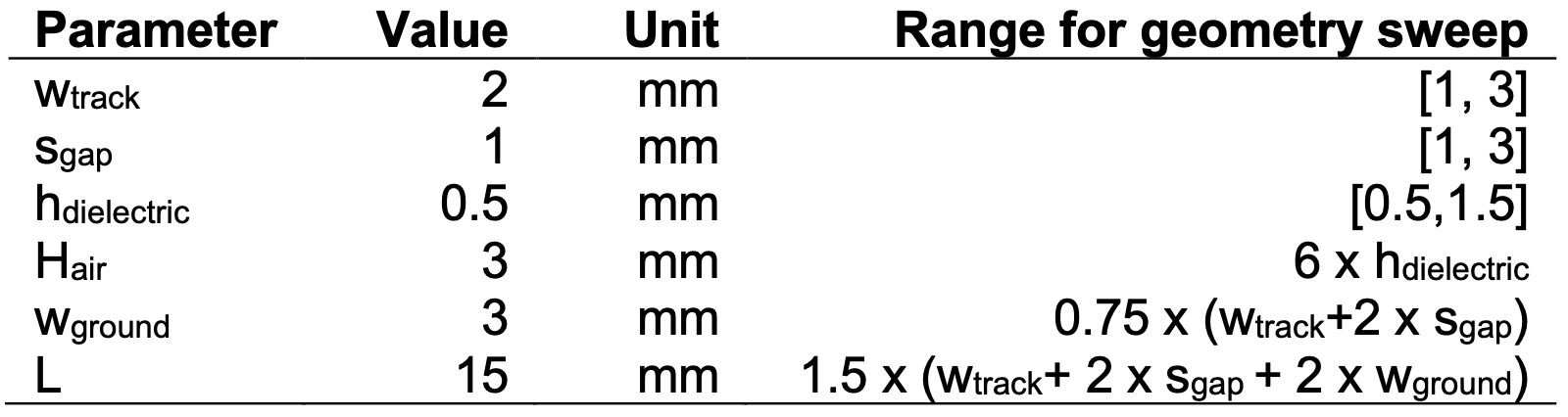
Fig. 3 Parameter definitions
The conductors are modeled as perfect electric conductors (PEC) using surface boundary conditions, an appropriate simplification for high-frequency simulations. The air domain surrounding the GCPW is also included in the simulation to accurately capture the electromagnetic field distribution. The size of the air domain is chosen as a function of the GCPW dimensions to minimize any influence of the outer simulation boundaries on the results.
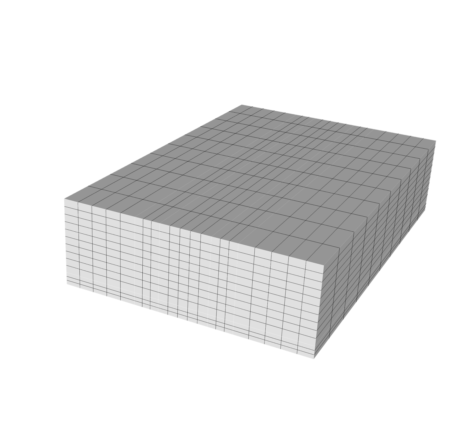
Fig. 4 Structured mesh
For the majority of the simulations, a structured mesh is employed. Structured meshes, where elements are arranged in a regular grid, are well-suited for the relatively simple geometry of the GCPW and offer high accuracy. The impact of different mesh types on the simulation accuracy, including a comparison with extruded and tetrahedral meshes.
Key results
The finite element simulations of the GCPW show results validated against analytical calculations, reveal the impact of different mesh types, and include parametric sweeps of key design parameters as well as a broad design exploration.
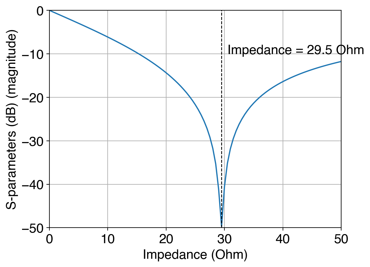
Fig. 5
Electric field magnitude Freq: 5 GHz
To validate the accuracy of the FEM simulations, the characteristic impedance of the GCPW is compared with the analytically calculated value. For the chosen nominal dimensions of the GCPW, the analytical characteristic impedance is approximately 31 Ω. Fig. 5 shows the simulated S-parameter magnitude as a function of the termination resistance at the lumped port. The minimum scattering, corresponding to the best impedance match, is observed at a resistance of approximately 29.5 Ω. This result is within 5% of the analytical value, demonstrating good agreement and validating the accuracy of the FEM simulation.
Mesh study
.png?width=797&height=251&name=meshes%20(1).png)
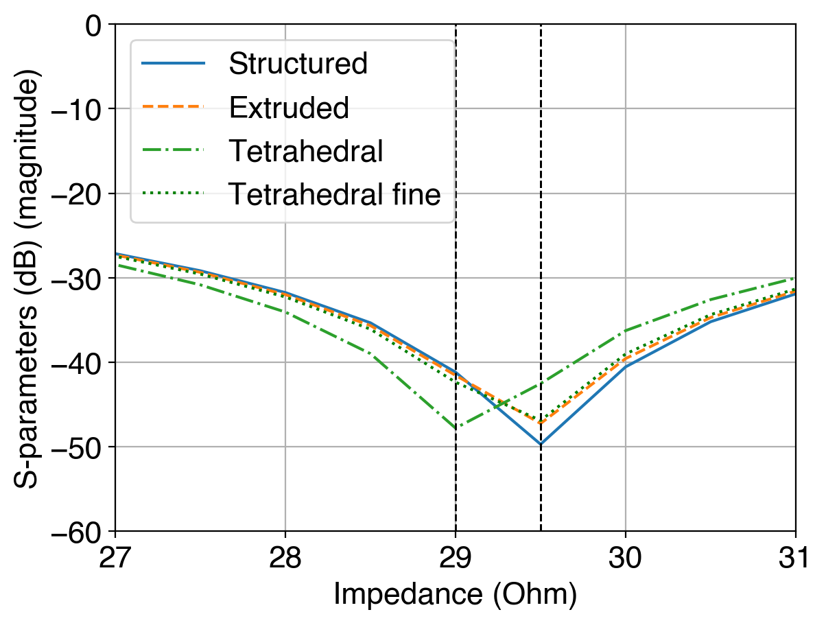
Fig. 6
The influence of different mesh types on the simulation accuracy is investigated by comparing the simulated characteristic impedance obtained using structured, extruded, and tetrahedral meshes. Fig. 6 presents these results. Both the structured and extruded meshes predict a characteristic impedance of approximately 29.5 Ω, consistent with the validation results. However, the tetrahedral mesh initially yields a slightly different impedance value. Upon refining the tetrahedral mesh by a factor of two, the simulated impedance converges to the same value obtained with the structured and extruded meshes. This demonstrates that while tetrahedral meshes can accurately capture the GCPW behavior, they may require a higher element count (and therefore more computational resources) to achieve the same level of accuracy as structured or extruded meshes for this particular geometry.
Parametric sweeps
Parametric sweeps are performed to investigate the impact of various design parameters on the GCPW's performance.
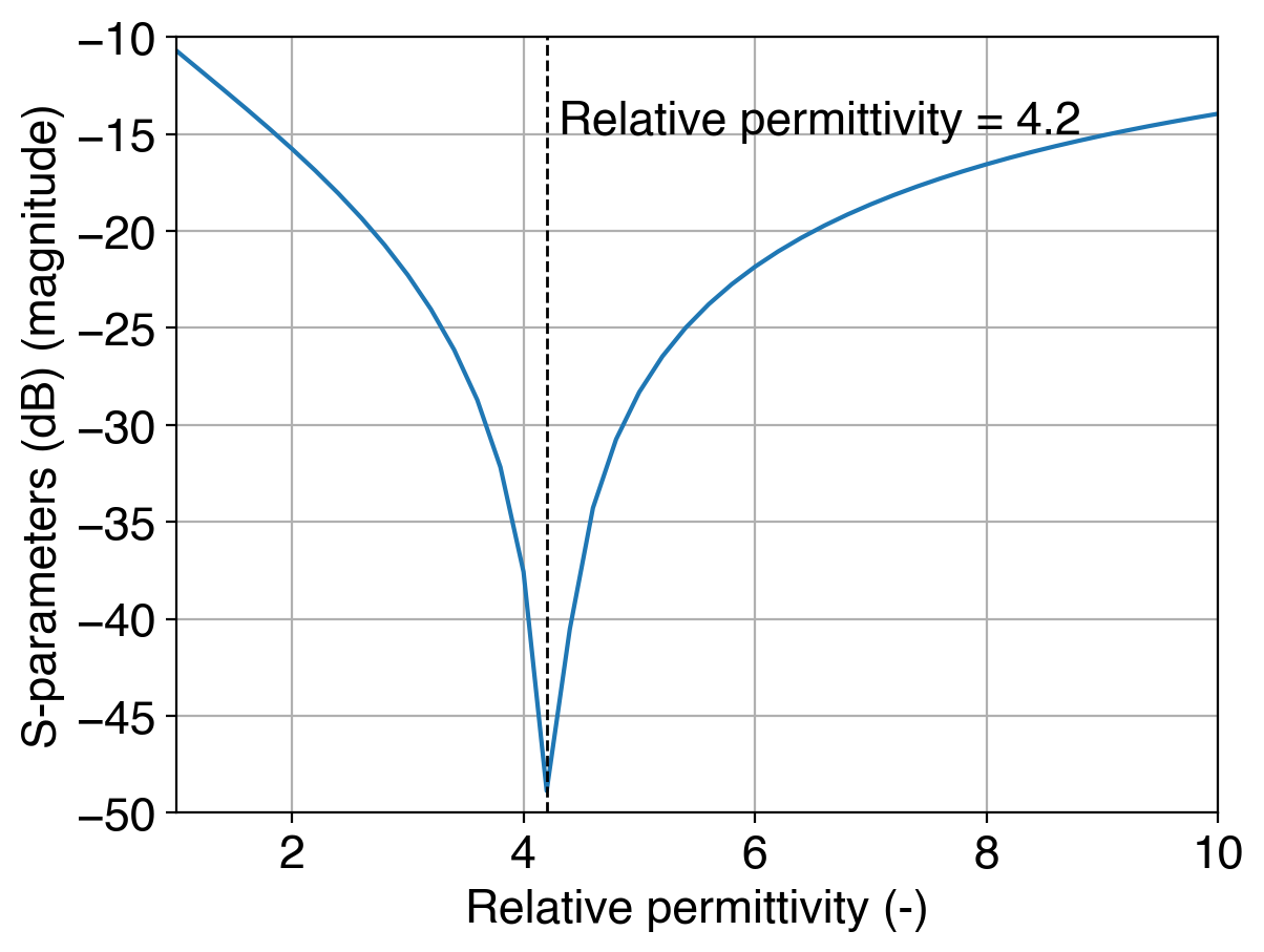
Fig. 7 Relative permittivity
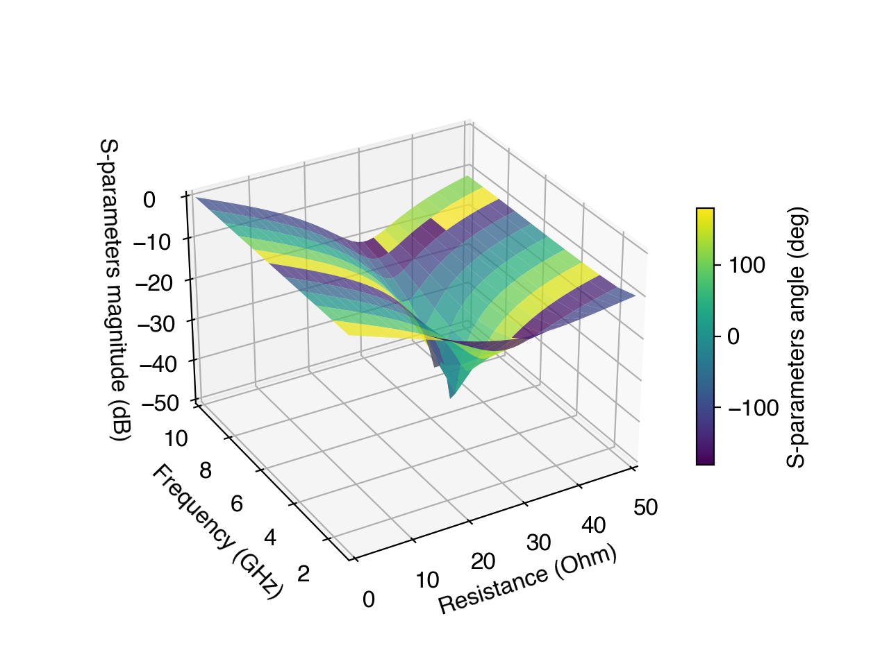
Fig. 8 Frequency sweep
- Relative permittivity: The effect of varying the relative permittivity of the dielectric substrate on the S-parameter response is demonstrated, showing noticeable shifts in resonance and transmission characteristics. The simulations reveal that a relative permittivity of approximately 4.2 yields the least scattering, which is close to the value of FR4 used in the other simulations.
- Frequency sweep: The results indicate that the GCPW exhibits the least scattering around 5 GHz, which corresponds to the resonance frequency of the RLC circuit connected to the lumped port.
Design exploration
A comprehensive design exploration study is conducted to understand the relationship between the GCPW's geometric parameters and its performance.
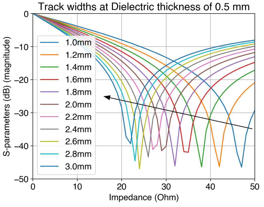
Fig. 9
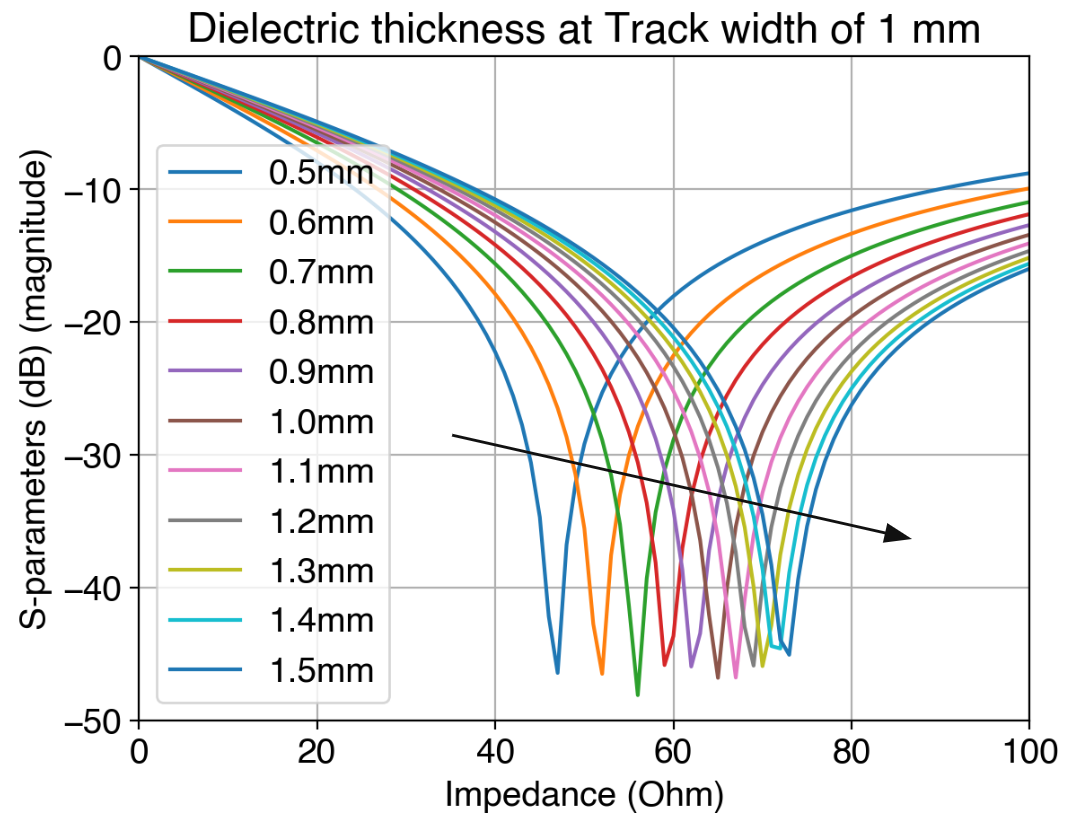
Fig. 10
- Track width variation: Fig. 9 shows the effect of varying the track width (w) on the characteristic impedance. As expected, increasing the track width decreases the impedance.
- Dielectric thickness variation: Fig. 10 shows the effect of varying the dielectric thickness (h) on the characteristic impedance. Increasing the dielectric thickness increases the impedance.
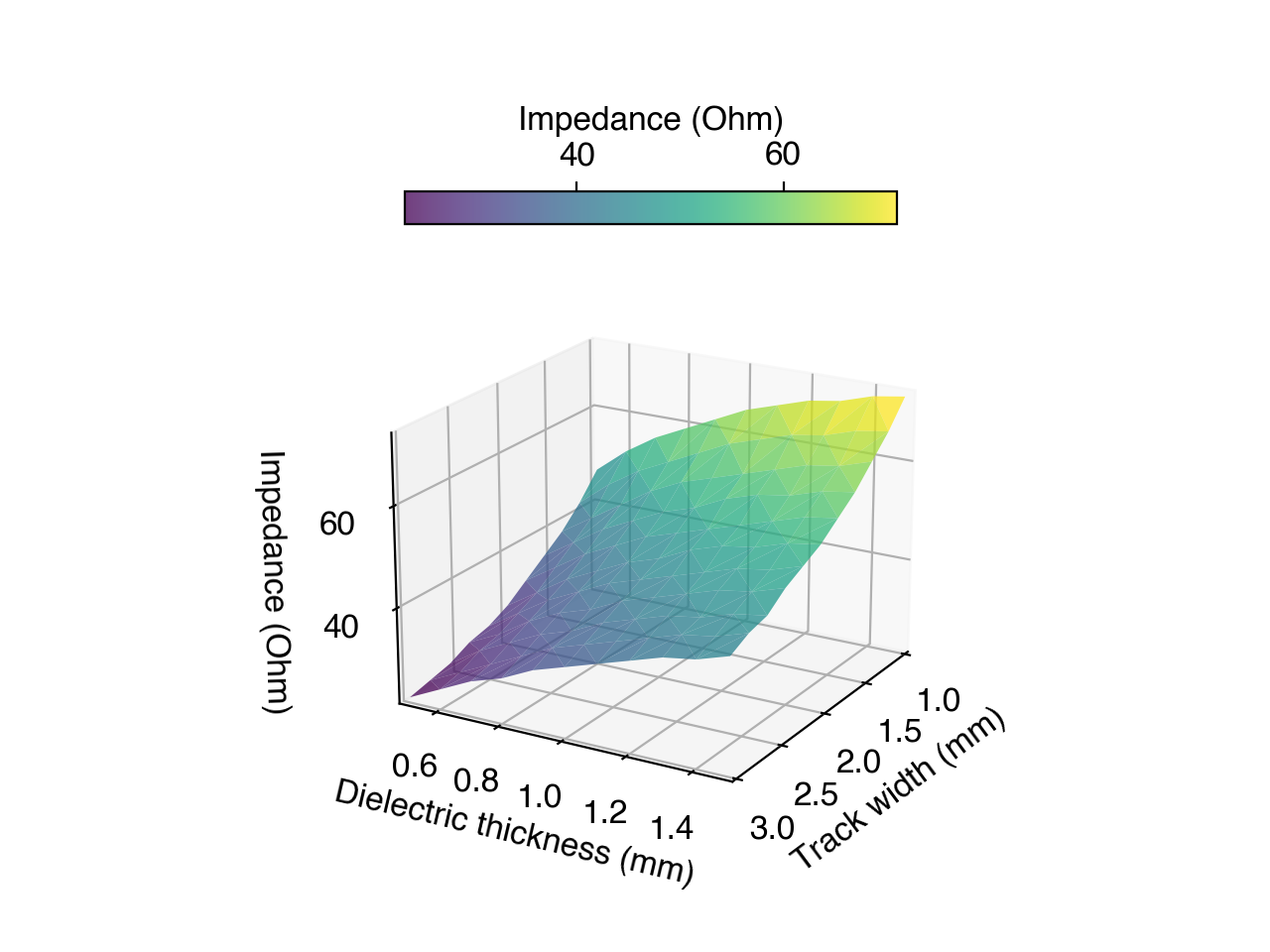
Fig. 11
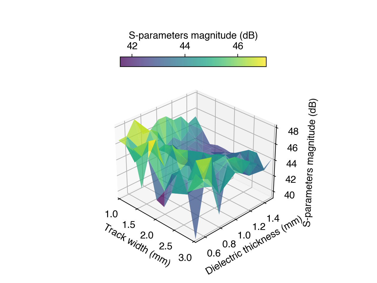
Fig. 12
- Combined track width and dielectric thickness variation: Fig. 11 explores the combined effect of track width and dielectric thickness on the characteristic impedance. The results reveal a slightly non-linear relationship between these parameters, highlighting the importance of considering their combined influence during the design process. The S-parameter magnitude for this combined sweep is shown in Fig. 12.
Key benefits demonstrated
Importantly, all these simulations, including the parametric sweeps and design exploration studies (amounting to approximately 12,000 simulations, each with half a million DoF), were completed efficiently using Quanscient Allsolve.
Each impedance sweep finished in less than a minute due to the platform's parallel processing capabilities. The entire design exploration study, which would have taken approximately nine days to complete sequentially on a single-core desktop computer, was completed in just 2-3 hours using Allsolve.
This dramatic speedup demonstrates the power and efficiency of cloud-based high-performance computing for complex electromagnetic simulations and design optimization.
Key findings of this study include:
- Excellent agreement between simulated and analytically calculated characteristic impedance, validating the accuracy of the FEM approach.
- A detailed analysis of the effects of different mesh types on simulation results, highlighting the efficiency of structured meshes for this specific geometry.
- Comprehensive parametric sweeps revealing the influence of key design parameters, such as relative permittivity, frequency, track width, and dielectric thickness, on GCPW performance.
- A thorough design exploration study demonstrating the complex interplay between geometric parameters and characteristic impedance.
Crucially, this work showcases the power and efficiency of Quanscient Allsolve for tackling computationally intensive electromagnetic simulations. The platform's cloud-based architecture and parallel processing capabilities enabled the completion of a large-scale design exploration study, involving approximately 12,000 simulations, in a fraction of the time it would have taken using traditional desktop-based computing.
This dramatic acceleration of the design cycle underscores the value of cloud-based high-performance computing for optimizing complex high-frequency components like GCPWs. Quanscient Allsolve's ability to automate complex simulations and parametric sweeps further enhances its utility for design exploration and optimization, making it a valuable tool for engineers working in high-frequency electronics and related fields.
Conclusion
We have demonstrated the application of finite element method (FEM) simulations for the analysis and design exploration of 3D grounded coplanar waveguides (GCPWs) using Quanscient Allsolve, a cloud-based multiphysics simulation platform.
We have shown how FEM simulations can be effectively used to understand the electromagnetic behavior of GCPWs, validate theoretical calculations, and explore the impact of various design parameters on their performance.